![]()
Author
Ivan Podadera Aliseda
Subject
RFQCB trailer for FRIATEC insulators
Prepared For
CERN-ISOLDE
Project Created
Friday, November 28, 2003 at 6:43:03 PM
Project Last Modified
Monday, December 01, 2003 at 10:45:27 AM
Report Created
Monday, December 01, 2003 at 10:49:40 AM
Software Used
Database
C:\RFQ mechanical drawings\Inventor\DOUBLE_TRAILER (FRIATEC) FOR DS.dsdb
This report documents design and analysis information created and maintained using the ANSYS® engineering software program. Each scenario listed below represents one complete engineering simulation.
Scenario 1
The ANSYS CAE (Computer-Aided Engineering) software program was used in conjunction with 3D CAD (Computer-Aided Design) solid geometry to simulate the behavior of mechanical bodies under thermal/structural loading conditions. ANSYS automated FEA (Finite Element Analysis) technologies from ANSYS, Inc. to generate the results listed in this report.
Each scenario presented below represents one complete engineering simulation. The definition of a simulation includes known factors about a design such as material properties per body, contact behavior between bodies (in an assembly), and types and magnitudes of loading conditions. The results of a simulation provide insight into how the bodies may perform and how the design might be improved. Multiple scenarios allow comparison of results given different loading conditions, materials or geometric configurations.
Convergence and alert criteria may be defined for any of the results and can serve as guides for evaluating the quality of calculated results and the acceptability of values in the context of known design requirements.
The discussions below follow the organization of information in the ANSYS "Explorer" user interface. Each scenario corresponds to a unique branch in the Explorer "Outline". Names emphasized in "double quotes" match preferences set in the user interface.
All values are presented in the "SI Metric (m, kg, Pa, °C, s)" unit system.
Notice
Do not accept or reject a design based solely on the data presented in this report. Evaluate designs by considering this information in conjunction with experimental test data and the practical experience of design engineers and analysts. A quality approach to engineering design usually mandates physical testing as the final means of validating structural integrity to a measured precision.
"Model" obtains geometry from the Inventor assembly "C:\RFQ mechanical drawings\Inventor\DOUBLE_TRAILER (FRIATEC) FOR DS.iam".
| Name | Material | Bounding Box (m) | Mass (kg) | Volume (m�) | Nodes | Elements |
|---|---|---|---|---|---|---|
| "SUPPORT_INSULATOR_1" | "Stainless Steel" | 0.18, 6.0×10⁻³, 0.18 | 1.43 | 1.85×10⁻⁴ | 997 | 122 |
| "SUPPORT_INSULATOR_2" | "Stainless Steel" | 0.18, 6.0×10⁻³, 0.18 | 1.43 | 1.85×10⁻⁴ | 1002 | 122 |
| "COLD-FINISHED HOLLOW SECTION - ISO 4019 - 60 X 60 X 3.2_8" | "Stainless Steel" | 0.06, 0.59, 6.0×10⁻² | 3.14 | 4.05×10⁻⁴ | 1464 | 192 |
| "COLD-FINISHED HOLLOW SECTION - ISO 4019 - 60 X 60 X 3.2_7" | "Stainless Steel" | 0.06, 0.59, 6.0×10⁻² | 3.14 | 4.05×10⁻⁴ | 1464 | 192 |
| "COLD-FINISHED HOLLOW SECTION - ISO 4019 - 60 X 60 X 3.2_6" | "Stainless Steel" | 0.06, 0.59, 6.0×10⁻² | 3.14 | 4.05×10⁻⁴ | 1464 | 192 |
| "COLD-FINISHED HOLLOW SECTION - ISO 4019 - 60 X 60 X 3.2_4" | "Stainless Steel" | 0.06, 0.59, 6.0×10⁻² | 3.14 | 4.05×10⁻⁴ | 1464 | 192 |
| "COLD-FINISHED HOLLOW SECTION - ISO 4019 - 60 X 60 X 3.2_5" | "Stainless Steel" | 0.06, 0.59, 6.0×10⁻² | 3.14 | 4.05×10⁻⁴ | 1464 | 192 |
| "COLD-FINISHED HOLLOW SECTION - ISO 4019 - 60 X 60 X 3.2_3" | "Stainless Steel" | 0.06, 0.59, 6.0×10⁻² | 3.14 | 4.05×10⁻⁴ | 1464 | 192 |
| "COLD-FINISHED HOLLOW SECTION - ISO 4019 - 60 X 60 X 3.2_2" | "Stainless Steel" | 0.06, 0.59, 6.0×10⁻² | 3.14 | 4.05×10⁻⁴ | 1464 | 192 |
| "COLD-FINISHED HOLLOW SECTION - ISO 4019 - 60 X 60 X 3.2_1" | "Stainless Steel" | 0.06, 0.59, 6.0×10⁻² | 3.14 | 4.05×10⁻⁴ | 1464 | 192 |
| "~~~~~COLD-FINISHED HOLLOW SECTION - ISO 4019 - 60 X 60 X 5.0_2" | "Stainless Steel" | 0.52, 0.06, 6.0×10⁻² | 4.09 | 5.27×10⁻⁴ | 976 | 128 |
| "~~~~~COLD-FINISHED HOLLOW SECTION - ISO 4019 - 60 X 60 X 5.0_1" | "Stainless Steel" | 0.52, 0.06, 6.0×10⁻² | 4.09 | 5.27×10⁻⁴ | 976 | 128 |
| "~~~~COLD-FINISHED HOLLOW SECTION - ISO 4019 - 60 X 60 X 5.0_2" | "Stainless Steel" | 0.06, 0.06, 1.51 | 11.77 | 1.52×10⁻³ | 12529 | 6598 |
| "~~~~COLD-FINISHED HOLLOW SECTION - ISO 4019 - 60 X 60 X 5.0_1" | "Stainless Steel" | 0.06, 0.06, 1.51 | 11.77 | 1.52×10⁻³ | 11434 | 6006 |
| "~COLD-FINISHED HOLLOW SECTION - ISO 4019 - 60 X 60 X 3.2_1" | "Stainless Steel" | 0.52, 0.06, 6.0×10⁻² | 2.78 | 3.58×10⁻⁴ | 7207 | 3566 |
| "~~COLD-FINISHED HOLLOW SECTION - ISO 4019 - 60 X 60 X 3.2_1" | "Stainless Steel" | 0.06, 0.06, 1.51 | 8.05 | 1.04×10⁻³ | 26678 | 15579 |
| "~~COLD-FINISHED HOLLOW SECTION - ISO 4019 - 60 X 60 X 3.2_2" | "Stainless Steel" | 0.06, 0.06, 1.51 | 8.05 | 1.04×10⁻³ | 20327 | 11053 |
| "~COLD-FINISHED HOLLOW SECTION - ISO 4019 - 60 X 60 X 3.2_3" | "Stainless Steel" | 0.52, 0.06, 6.0×10⁻² | 2.78 | 3.58×10⁻⁴ | 7148 | 3532 |
| "COLD-2 60X60X3.2_1" | "Stainless Steel" | 0.52, 0.06, 6.0×10⁻² | 2.79 | 3.6×10⁻⁴ | 1464 | 192 |
| "SUPPORT_INSULATOR_3" | "Stainless Steel" | 0.18, 6.0×10⁻³, 0.18 | 1.43 | 1.85×10⁻⁴ | 995 | 121 |
| "SUPPORT_INSULATOR_4" | "Stainless Steel" | 0.18, 6.0×10⁻³, 0.18 | 1.43 | 1.85×10⁻⁴ | 899 | 108 |
| Name | Type | Origin (m) | X Axis | Y Axis | Z Axis | Comments | Figures |
|---|---|---|---|---|---|---|---|
| "Global Coordinate System" | Cartesian | 0.0, 0.0, 0.0 | 1.0, 0.0, 0.0 | 0.0, 1.0, 0.0 | 0.0, 0.0, 1.0 | None | None |
| Name | Type | Associated Bodies | Normal Stiffness | Scope Mode | Behavior | Formulation | Initial Interface Treatment | Thermal Conductance |
|---|---|---|---|---|---|---|---|---|
| "Contact Region" | Bonded | "SUPP_INSUL_1" and "REGULATION2_1" | Program Controlled | Automatic | Symmetric | Pure Penalty | Adjusted to Touch | Program Controlled |
| "Contact Region 2" | Bonded | "SUPP_INSUL_2" and "REGULATION2_1" | Program Controlled | Automatic | Symmetric | Pure Penalty | Adjusted to Touch | Program Controlled |
| "Contact Region 3" | Bonded | "SUPP_INSUL_3" and "REGULATION2_1" | Program Controlled | Automatic | Symmetric | Pure Penalty | Adjusted to Touch | Program Controlled |
| "Contact Region 4" | Bonded | "SUPP_INSUL_4" and "REGULATION2_1" | Program Controlled | Automatic | Symmetric | Pure Penalty | Adjusted to Touch | Program Controlled |
| "Contact Region 5" | Bonded | "SUPPORT_INSULATOR_1" and "SUPP_INSUL_1" | Program Controlled | Automatic | Symmetric | Pure Penalty | Adjusted to Touch | Program Controlled |
| "Contact Region 6" | Bonded | "SUPPORT_INSULATOR_2" and "SUPP_INSUL_2" | Program Controlled | Automatic | Symmetric | Pure Penalty | Adjusted to Touch | Program Controlled |
| "Contact Region 7" | Bonded | "SUPPORT_INSULATOR_4" and "SUPP_INSUL_3" | Program Controlled | Automatic | Symmetric | Pure Penalty | Adjusted to Touch | Program Controlled |
| "Contact Region 8" | Bonded | "SUPPORT_INSULATOR_3" and "SUPP_INSUL_4" | Program Controlled | Automatic | Symmetric | Pure Penalty | Adjusted to Touch | Program Controlled |
| "Contact Region 9" | Bonded | "~COLD-FINISHED HOLLOW SECTION - ISO 4019 - 60 X 60 X 3.2_1" and "SUPPORT_INSULATOR_1" | Program Controlled | Automatic | Symmetric | Pure Penalty | Adjusted to Touch | Program Controlled |
| "Contact Region 10" | Bonded | "~~COLD-FINISHED HOLLOW SECTION - ISO 4019 - 60 X 60 X 3.2_1" and "SUPPORT_INSULATOR_1" | Program Controlled | Automatic | Symmetric | Pure Penalty | Adjusted to Touch | Program Controlled |
| "Contact Region 11" | Bonded | "~~COLD-FINISHED HOLLOW SECTION - ISO 4019 - 60 X 60 X 3.2_1" and "SUPPORT_INSULATOR_2" | Program Controlled | Automatic | Symmetric | Pure Penalty | Adjusted to Touch | Program Controlled |
| "Contact Region 12" | Bonded | "~COLD-FINISHED HOLLOW SECTION - ISO 4019 - 60 X 60 X 3.2_3" and "SUPPORT_INSULATOR_2" | Program Controlled | Automatic | Symmetric | Pure Penalty | Adjusted to Touch | Program Controlled |
| "Contact Region 13" | Bonded | "JOINT2_1" and "FIXING_3" | Program Controlled | Automatic | Symmetric | Pure Penalty | Adjusted to Touch | Program Controlled |
| "Contact Region 14" | Bonded | "HEX-HEAD BOLT - ISO 4017 - M10X90_1" and "FIXING_3" | Program Controlled | Automatic | Symmetric | Pure Penalty | Adjusted to Touch | Program Controlled |
| "Contact Region 15" | Bonded | "PARALLEL PIN - ISO 2338 - 6 M6 X 32 - A_1" and "FIXING_3" | Program Controlled | Automatic | Symmetric | Pure Penalty | Adjusted to Touch | Program Controlled |
| "Contact Region 16" | Bonded | "JOINT2_1" and "JOINT_1" | Program Controlled | Automatic | Symmetric | Pure Penalty | Adjusted to Touch | Program Controlled |
| "Contact Region 17" | Bonded | "~~~~COLD-FINISHED HOLLOW SECTION - ISO 4019 - 60 X 60 X 5.0_2" and "JOINT_1" | Program Controlled | Automatic | Symmetric | Pure Penalty | Adjusted to Touch | Program Controlled |
| "Contact Region 18" | Bonded | "HEX NUT - ISO 4032 - M10_1" and "JOINT2_1" | Program Controlled | Automatic | Symmetric | Pure Penalty | Adjusted to Touch | Program Controlled |
| "Contact Region 19" | Bonded | "HEX-HEAD BOLT - ISO 4017 - M10X90_1" and "JOINT2_1" | Program Controlled | Automatic | Symmetric | Pure Penalty | Adjusted to Touch | Program Controlled |
| "Contact Region 20" | Bonded | "PARALLEL PIN - ISO 2338 - 6 M6 X 32 - A_1" and "JOINT2_1" | Program Controlled | Automatic | Symmetric | Pure Penalty | Adjusted to Touch | Program Controlled |
| "Contact Region 21" | Bonded | "COLD-FINISHED HOLLOW SECTION - ISO 4019 - 60 X 60 X 3.2_3" and "JOINT2_1" | Program Controlled | Automatic | Symmetric | Pure Penalty | Adjusted to Touch | Program Controlled |
| "Contact Region 22" | Bonded | "~~~~~COLD-FINISHED HOLLOW SECTION - ISO 4019 - 60 X 60 X 5.0_1" and "JOINT2_1" | Program Controlled | Automatic | Symmetric | Pure Penalty | Adjusted to Touch | Program Controlled |
| "Contact Region 23" | Bonded | "~~~~COLD-FINISHED HOLLOW SECTION - ISO 4019 - 60 X 60 X 5.0_2" and "JOINT2_1" | Program Controlled | Automatic | Symmetric | Pure Penalty | Adjusted to Touch | Program Controlled |
| "Contact Region 24" | Bonded | "HEX-HEAD BOLT - ISO 4017 - M10X90_1" and "HEX NUT - ISO 4032 - M10_1" | Program Controlled | Automatic | Symmetric | Pure Penalty | Adjusted to Touch | Program Controlled |
| "Contact Region 25" | Bonded | "JOINT2_1 (2)" and "FIXING_3 (2)" | Program Controlled | Automatic | Symmetric | Pure Penalty | Adjusted to Touch | Program Controlled |
| "Contact Region 26" | Bonded | "HEX-HEAD BOLT - ISO 4017 - M10X90_1 (2)" and "FIXING_3 (2)" | Program Controlled | Automatic | Symmetric | Pure Penalty | Adjusted to Touch | Program Controlled |
| "Contact Region 27" | Bonded | "PARALLEL PIN - ISO 2338 - 6 M6 X 32 - A_1 (2)" and "FIXING_3 (2)" | Program Controlled | Automatic | Symmetric | Pure Penalty | Adjusted to Touch | Program Controlled |
| "Contact Region 28" | Bonded | "JOINT2_1 (2)" and "JOINT_1 (2)" | Program Controlled | Automatic | Symmetric | Pure Penalty | Adjusted to Touch | Program Controlled |
| "Contact Region 29" | Bonded | "~~~~COLD-FINISHED HOLLOW SECTION - ISO 4019 - 60 X 60 X 5.0_1" and "JOINT_1 (2)" | Program Controlled | Automatic | Symmetric | Pure Penalty | Adjusted to Touch | Program Controlled |
| "Contact Region 30" | Bonded | "HEX NUT - ISO 4032 - M10_1 (2)" and "JOINT2_1 (2)" | Program Controlled | Automatic | Symmetric | Pure Penalty | Adjusted to Touch | Program Controlled |
| "Contact Region 31" | Bonded | "HEX-HEAD BOLT - ISO 4017 - M10X90_1 (2)" and "JOINT2_1 (2)" | Program Controlled | Automatic | Symmetric | Pure Penalty | Adjusted to Touch | Program Controlled |
| "Contact Region 32" | Bonded | "PARALLEL PIN - ISO 2338 - 6 M6 X 32 - A_1 (2)" and "JOINT2_1 (2)" | Program Controlled | Automatic | Symmetric | Pure Penalty | Adjusted to Touch | Program Controlled |
| "Contact Region 33" | Bonded | "~~~~~COLD-FINISHED HOLLOW SECTION - ISO 4019 - 60 X 60 X 5.0_1" and "JOINT2_1 (2)" | Program Controlled | Automatic | Symmetric | Pure Penalty | Adjusted to Touch | Program Controlled |
| "Contact Region 34" | Bonded | "~~~~COLD-FINISHED HOLLOW SECTION - ISO 4019 - 60 X 60 X 5.0_1" and "JOINT2_1 (2)" | Program Controlled | Automatic | Symmetric | Pure Penalty | Adjusted to Touch | Program Controlled |
| "Contact Region 35" | Bonded | "HEX-HEAD BOLT - ISO 4017 - M10X90_1 (2)" and "HEX NUT - ISO 4032 - M10_1 (2)" | Program Controlled | Automatic | Symmetric | Pure Penalty | Adjusted to Touch | Program Controlled |
| "Contact Region 36" | Bonded | "JOINT2_1 (3)" and "FIXING_3 (3)" | Program Controlled | Automatic | Symmetric | Pure Penalty | Adjusted to Touch | Program Controlled |
| "Contact Region 37" | Bonded | "HEX-HEAD BOLT - ISO 4017 - M10X90_1 (3)" and "FIXING_3 (3)" | Program Controlled | Automatic | Symmetric | Pure Penalty | Adjusted to Touch | Program Controlled |
| "Contact Region 38" | Bonded | "PARALLEL PIN - ISO 2338 - 6 M6 X 32 - A_1 (3)" and "FIXING_3 (3)" | Program Controlled | Automatic | Symmetric | Pure Penalty | Adjusted to Touch | Program Controlled |
| "Contact Region 39" | Bonded | "JOINT2_1 (3)" and "JOINT_1 (3)" | Program Controlled | Automatic | Symmetric | Pure Penalty | Adjusted to Touch | Program Controlled |
| "Contact Region 40" | Bonded | "~~~~~COLD-FINISHED HOLLOW SECTION - ISO 4019 - 60 X 60 X 5.0_2" and "JOINT_1 (3)" | Program Controlled | Automatic | Symmetric | Pure Penalty | Adjusted to Touch | Program Controlled |
| "Contact Region 41" | Bonded | "HEX NUT - ISO 4032 - M10_1 (3)" and "JOINT2_1 (3)" | Program Controlled | Automatic | Symmetric | Pure Penalty | Adjusted to Touch | Program Controlled |
| "Contact Region 42" | Bonded | "HEX-HEAD BOLT - ISO 4017 - M10X90_1 (3)" and "JOINT2_1 (3)" | Program Controlled | Automatic | Symmetric | Pure Penalty | Adjusted to Touch | Program Controlled |
| "Contact Region 43" | Bonded | "PARALLEL PIN - ISO 2338 - 6 M6 X 32 - A_1 (3)" and "JOINT2_1 (3)" | Program Controlled | Automatic | Symmetric | Pure Penalty | Adjusted to Touch | Program Controlled |
| "Contact Region 44" | Bonded | "~~~~~COLD-FINISHED HOLLOW SECTION - ISO 4019 - 60 X 60 X 5.0_2" and "JOINT2_1 (3)" | Program Controlled | Automatic | Symmetric | Pure Penalty | Adjusted to Touch | Program Controlled |
| "Contact Region 45" | Bonded | "HEX-HEAD BOLT - ISO 4017 - M10X90_1 (3)" and "HEX NUT - ISO 4032 - M10_1 (3)" | Program Controlled | Automatic | Symmetric | Pure Penalty | Adjusted to Touch | Program Controlled |
| "Contact Region 46" | Bonded | "~~~~COLD-FINISHED HOLLOW SECTION - ISO 4019 - 60 X 60 X 5.0_2" and "COLD-FINISHED HOLLOW SECTION - ISO 4019 - 60 X 60 X 3.2_8" | Program Controlled | Automatic | Symmetric | Pure Penalty | Adjusted to Touch | Program Controlled |
| "Contact Region 47" | Bonded | "~~COLD-FINISHED HOLLOW SECTION - ISO 4019 - 60 X 60 X 3.2_1" and "COLD-FINISHED HOLLOW SECTION - ISO 4019 - 60 X 60 X 3.2_8" | Program Controlled | Automatic | Symmetric | Pure Penalty | Adjusted to Touch | Program Controlled |
| "Contact Region 48" | Bonded | "SUPPORT_ELECT_1" and "COLD-FINISHED HOLLOW SECTION - ISO 4019 - 60 X 60 X 3.2_8" | Program Controlled | Automatic | Symmetric | Pure Penalty | Adjusted to Touch | Program Controlled |
| "Contact Region 49" | Bonded | "~~~~COLD-FINISHED HOLLOW SECTION - ISO 4019 - 60 X 60 X 5.0_2" and "COLD-FINISHED HOLLOW SECTION - ISO 4019 - 60 X 60 X 3.2_7" | Program Controlled | Automatic | Symmetric | Pure Penalty | Adjusted to Touch | Program Controlled |
| "Contact Region 50" | Bonded | "~~COLD-FINISHED HOLLOW SECTION - ISO 4019 - 60 X 60 X 3.2_1" and "COLD-FINISHED HOLLOW SECTION - ISO 4019 - 60 X 60 X 3.2_7" | Program Controlled | Automatic | Symmetric | Pure Penalty | Adjusted to Touch | Program Controlled |
| "Contact Region 51" | Bonded | "SUPPORT_ELECT_1" and "COLD-FINISHED HOLLOW SECTION - ISO 4019 - 60 X 60 X 3.2_7" | Program Controlled | Automatic | Symmetric | Pure Penalty | Adjusted to Touch | Program Controlled |
| "Contact Region 52" | Bonded | "~~~~COLD-FINISHED HOLLOW SECTION - ISO 4019 - 60 X 60 X 5.0_1" and "COLD-FINISHED HOLLOW SECTION - ISO 4019 - 60 X 60 X 3.2_6" | Program Controlled | Automatic | Symmetric | Pure Penalty | Adjusted to Touch | Program Controlled |
| "Contact Region 53" | Bonded | "~~COLD-FINISHED HOLLOW SECTION - ISO 4019 - 60 X 60 X 3.2_2" and "COLD-FINISHED HOLLOW SECTION - ISO 4019 - 60 X 60 X 3.2_6" | Program Controlled | Automatic | Symmetric | Pure Penalty | Adjusted to Touch | Program Controlled |
| "Contact Region 54" | Bonded | "SUPPORT_ELECT_1" and "COLD-FINISHED HOLLOW SECTION - ISO 4019 - 60 X 60 X 3.2_6" | Program Controlled | Automatic | Symmetric | Pure Penalty | Adjusted to Touch | Program Controlled |
| "Contact Region 55" | Bonded | "~~~~~COLD-FINISHED HOLLOW SECTION - ISO 4019 - 60 X 60 X 5.0_1" and "COLD-FINISHED HOLLOW SECTION - ISO 4019 - 60 X 60 X 3.2_4" | Program Controlled | Automatic | Symmetric | Pure Penalty | Adjusted to Touch | Program Controlled |
| "Contact Region 56" | Bonded | "~~~~COLD-FINISHED HOLLOW SECTION - ISO 4019 - 60 X 60 X 5.0_1" and "COLD-FINISHED HOLLOW SECTION - ISO 4019 - 60 X 60 X 3.2_4" | Program Controlled | Automatic | Symmetric | Pure Penalty | Adjusted to Touch | Program Controlled |
| "Contact Region 57" | Bonded | "~~COLD-FINISHED HOLLOW SECTION - ISO 4019 - 60 X 60 X 3.2_2" and "COLD-FINISHED HOLLOW SECTION - ISO 4019 - 60 X 60 X 3.2_4" | Program Controlled | Automatic | Symmetric | Pure Penalty | Adjusted to Touch | Program Controlled |
| "Contact Region 58" | Bonded | "~~~~COLD-FINISHED HOLLOW SECTION - ISO 4019 - 60 X 60 X 5.0_1" and "COLD-FINISHED HOLLOW SECTION - ISO 4019 - 60 X 60 X 3.2_5" | Program Controlled | Automatic | Symmetric | Pure Penalty | Adjusted to Touch | Program Controlled |
| "Contact Region 59" | Bonded | "~~COLD-FINISHED HOLLOW SECTION - ISO 4019 - 60 X 60 X 3.2_2" and "COLD-FINISHED HOLLOW SECTION - ISO 4019 - 60 X 60 X 3.2_5" | Program Controlled | Automatic | Symmetric | Pure Penalty | Adjusted to Touch | Program Controlled |
| "Contact Region 60" | Bonded | "SUPPORT_ELECT_1" and "COLD-FINISHED HOLLOW SECTION - ISO 4019 - 60 X 60 X 3.2_5" | Program Controlled | Automatic | Symmetric | Pure Penalty | Adjusted to Touch | Program Controlled |
| "Contact Region 61" | Bonded | "~~~~~COLD-FINISHED HOLLOW SECTION - ISO 4019 - 60 X 60 X 5.0_1" and "COLD-FINISHED HOLLOW SECTION - ISO 4019 - 60 X 60 X 3.2_3" | Program Controlled | Automatic | Symmetric | Pure Penalty | Adjusted to Touch | Program Controlled |
| "Contact Region 62" | Bonded | "~~~~COLD-FINISHED HOLLOW SECTION - ISO 4019 - 60 X 60 X 5.0_2" and "COLD-FINISHED HOLLOW SECTION - ISO 4019 - 60 X 60 X 3.2_3" | Program Controlled | Automatic | Symmetric | Pure Penalty | Adjusted to Touch | Program Controlled |
| "Contact Region 63" | Bonded | "~~COLD-FINISHED HOLLOW SECTION - ISO 4019 - 60 X 60 X 3.2_1" and "COLD-FINISHED HOLLOW SECTION - ISO 4019 - 60 X 60 X 3.2_3" | Program Controlled | Automatic | Symmetric | Pure Penalty | Adjusted to Touch | Program Controlled |
| "Contact Region 64" | Bonded | "~~~~~COLD-FINISHED HOLLOW SECTION - ISO 4019 - 60 X 60 X 5.0_2" and "COLD-FINISHED HOLLOW SECTION - ISO 4019 - 60 X 60 X 3.2_2" | Program Controlled | Automatic | Symmetric | Pure Penalty | Adjusted to Touch | Program Controlled |
| "Contact Region 65" | Bonded | "~~~~COLD-FINISHED HOLLOW SECTION - ISO 4019 - 60 X 60 X 5.0_2" and "COLD-FINISHED HOLLOW SECTION - ISO 4019 - 60 X 60 X 3.2_2" | Program Controlled | Automatic | Symmetric | Pure Penalty | Adjusted to Touch | Program Controlled |
| "Contact Region 66" | Bonded | "~~COLD-FINISHED HOLLOW SECTION - ISO 4019 - 60 X 60 X 3.2_1" and "COLD-FINISHED HOLLOW SECTION - ISO 4019 - 60 X 60 X 3.2_2" | Program Controlled | Automatic | Symmetric | Pure Penalty | Adjusted to Touch | Program Controlled |
| "Contact Region 67" | Bonded | "~~~~~COLD-FINISHED HOLLOW SECTION - ISO 4019 - 60 X 60 X 5.0_2" and "COLD-FINISHED HOLLOW SECTION - ISO 4019 - 60 X 60 X 3.2_1" | Program Controlled | Automatic | Symmetric | Pure Penalty | Adjusted to Touch | Program Controlled |
| "Contact Region 68" | Bonded | "~~~~COLD-FINISHED HOLLOW SECTION - ISO 4019 - 60 X 60 X 5.0_1" and "COLD-FINISHED HOLLOW SECTION - ISO 4019 - 60 X 60 X 3.2_1" | Program Controlled | Automatic | Symmetric | Pure Penalty | Adjusted to Touch | Program Controlled |
| "Contact Region 69" | Bonded | "~~COLD-FINISHED HOLLOW SECTION - ISO 4019 - 60 X 60 X 3.2_2" and "COLD-FINISHED HOLLOW SECTION - ISO 4019 - 60 X 60 X 3.2_1" | Program Controlled | Automatic | Symmetric | Pure Penalty | Adjusted to Touch | Program Controlled |
| "Contact Region 70" | Bonded | "~~~~COLD-FINISHED HOLLOW SECTION - ISO 4019 - 60 X 60 X 5.0_2" and "~~~~~COLD-FINISHED HOLLOW SECTION - ISO 4019 - 60 X 60 X 5.0_2" | Program Controlled | Automatic | Symmetric | Pure Penalty | Adjusted to Touch | Program Controlled |
| "Contact Region 71" | Bonded | "~~~~COLD-FINISHED HOLLOW SECTION - ISO 4019 - 60 X 60 X 5.0_1" and "~~~~~COLD-FINISHED HOLLOW SECTION - ISO 4019 - 60 X 60 X 5.0_2" | Program Controlled | Automatic | Symmetric | Pure Penalty | Adjusted to Touch | Program Controlled |
| "Contact Region 72" | Bonded | "~~~~COLD-FINISHED HOLLOW SECTION - ISO 4019 - 60 X 60 X 5.0_2" and "~~~~~COLD-FINISHED HOLLOW SECTION - ISO 4019 - 60 X 60 X 5.0_1" | Program Controlled | Automatic | Symmetric | Pure Penalty | Adjusted to Touch | Program Controlled |
| "Contact Region 73" | Bonded | "~~~~COLD-FINISHED HOLLOW SECTION - ISO 4019 - 60 X 60 X 5.0_1" and "~~~~~COLD-FINISHED HOLLOW SECTION - ISO 4019 - 60 X 60 X 5.0_1" | Program Controlled | Automatic | Symmetric | Pure Penalty | Adjusted to Touch | Program Controlled |
| "Contact Region 74" | Bonded | "SUPPORT_ELECT_1" and "~~~~COLD-FINISHED HOLLOW SECTION - ISO 4019 - 60 X 60 X 5.0_2" | Program Controlled | Automatic | Symmetric | Pure Penalty | Adjusted to Touch | Program Controlled |
| "Contact Region 75" | Bonded | "SUPPORT_ELECT_1" and "~~~~COLD-FINISHED HOLLOW SECTION - ISO 4019 - 60 X 60 X 5.0_1" | Program Controlled | Automatic | Symmetric | Pure Penalty | Adjusted to Touch | Program Controlled |
| "Contact Region 76" | Bonded | "~~COLD-FINISHED HOLLOW SECTION - ISO 4019 - 60 X 60 X 3.2_1" and "~COLD-FINISHED HOLLOW SECTION - ISO 4019 - 60 X 60 X 3.2_1" | Program Controlled | Automatic | Symmetric | Pure Penalty | Adjusted to Touch | Program Controlled |
| "Contact Region 77" | Bonded | "~~COLD-FINISHED HOLLOW SECTION - ISO 4019 - 60 X 60 X 3.2_2" and "~COLD-FINISHED HOLLOW SECTION - ISO 4019 - 60 X 60 X 3.2_1" | Program Controlled | Automatic | Symmetric | Pure Penalty | Adjusted to Touch | Program Controlled |
| "Contact Region 78" | Bonded | "SUPPORT_INSULATOR_4" and "~COLD-FINISHED HOLLOW SECTION - ISO 4019 - 60 X 60 X 3.2_1" | Program Controlled | Automatic | Symmetric | Pure Penalty | Adjusted to Touch | Program Controlled |
| "Contact Region 79" | Bonded | "~COLD-FINISHED HOLLOW SECTION - ISO 4019 - 60 X 60 X 3.2_3" and "~~COLD-FINISHED HOLLOW SECTION - ISO 4019 - 60 X 60 X 3.2_1" | Program Controlled | Automatic | Symmetric | Pure Penalty | Adjusted to Touch | Program Controlled |
| "Contact Region 80" | Bonded | "COLD-2 60X60X3.2_1" and "~~COLD-FINISHED HOLLOW SECTION - ISO 4019 - 60 X 60 X 3.2_1" | Program Controlled | Automatic | Symmetric | Pure Penalty | Adjusted to Touch | Program Controlled |
| "Contact Region 81" | Bonded | "~COLD-FINISHED HOLLOW SECTION - ISO 4019 - 60 X 60 X 3.2_3" and "~~COLD-FINISHED HOLLOW SECTION - ISO 4019 - 60 X 60 X 3.2_2" | Program Controlled | Automatic | Symmetric | Pure Penalty | Adjusted to Touch | Program Controlled |
| "Contact Region 82" | Bonded | "COLD-2 60X60X3.2_1" and "~~COLD-FINISHED HOLLOW SECTION - ISO 4019 - 60 X 60 X 3.2_2" | Program Controlled | Automatic | Symmetric | Pure Penalty | Adjusted to Touch | Program Controlled |
| "Contact Region 83" | Bonded | "SUPPORT_INSULATOR_3" and "~~COLD-FINISHED HOLLOW SECTION - ISO 4019 - 60 X 60 X 3.2_2" | Program Controlled | Automatic | Symmetric | Pure Penalty | Adjusted to Touch | Program Controlled |
| "Contact Region 84" | Bonded | "SUPPORT_INSULATOR_4" and "~~COLD-FINISHED HOLLOW SECTION - ISO 4019 - 60 X 60 X 3.2_2" | Program Controlled | Automatic | Symmetric | Pure Penalty | Adjusted to Touch | Program Controlled |
| "Contact Region 85" | Bonded | "SUPPORT_INSULATOR_3" and "~COLD-FINISHED HOLLOW SECTION - ISO 4019 - 60 X 60 X 3.2_3" | Program Controlled | Automatic | Symmetric | Pure Penalty | Adjusted to Touch | Program Controlled |
"Environment" contains all loading conditions defined for "Model" in this scenario.
Standard Earth Gravity
The following tables list local loads and supports applied to specific geometry.
"Solution" contains the calculated response for "Model" given loading conditions defined in "Environment".
It was selected that the program would choose the solver used in this solution.
| Name | Scope | Minimum | Maximum | Alert Criteria |
|---|---|---|---|---|
| "Equivalent Stress" | All Bodies In "Model" | 249.36 Pa | 7.37×10⁶ Pa | None |
| "Total Deformation" | All Bodies In "Model" | 0.0 m | 1.97×10⁻⁵ m | None |
| Name | Type | Value |
|---|---|---|
| Modulus of Elasticity | Temperature-Independent | 2.0×10¹¹ Pa |
| Poisson's Ratio | Temperature-Independent | 0.3 |
| Mass Density | Temperature-Independent | 7,850.0 kg/m� |
| Coefficient of Thermal Expansion | Temperature-Independent | 1.2×10⁻⁵ 1/�C |
| Thermal Conductivity | Temperature-Independent | 60.5 W/m��C | Specific Heat | Temperature-Independent | 434.0 J/kg��C |
| Name | Type | Value |
|---|---|---|
| Tensile Yield Strength | Temperature-Independent | 2.5×10⁸ Pa |
| Tensile Ultimate Strength | Temperature-Independent | 4.6×10⁸ Pa |
| Compressive Yield Strength | Temperature-Independent | 2.5×10⁸ Pa |
| Compressive Ultimate Strength | Temperature-Independent | 0.0 Pa |
 |
 |
| Name | Type | Value |
|---|---|---|
| Modulus of Elasticity | Temperature-Independent | 1.93×10¹¹ Pa |
| Poisson's Ratio | Temperature-Independent | 0.31 |
| Mass Density | Temperature-Independent | 7,750.0 kg/m� |
| Coefficient of Thermal Expansion | Temperature-Independent | 1.36×10⁻⁵ 1/�C |
| Thermal Conductivity | Temperature-Independent | 15.1 W/m��C | Specific Heat | Temperature-Independent | 480.0 J/kg��C |
| Name | Type | Value |
|---|---|---|
| Tensile Yield Strength | Temperature-Independent | 2.07×10⁸ Pa |
| Tensile Ultimate Strength | Temperature-Independent | 5.86×10⁸ Pa |
| Compressive Yield Strength | Temperature-Independent | 2.07×10⁸ Pa |
| Compressive Ultimate Strength | Temperature-Independent | 0.0 Pa |
 |
| Name | Type | Value |
|---|---|---|
| Modulus of Elasticity | Temperature-Independent | 2.9×10⁹ Pa |
| Poisson's Ratio | Temperature-Independent | 0.35 |
| Mass Density | Temperature-Independent | 1,420.0 kg/m� |
| Coefficient of Thermal Expansion | Temperature-Independent | 0.0 1/�C | Specific Heat | Temperature-Independent | 0.0 J/kg��C |
| Name | Type | Value |
|---|---|---|
| Tensile Yield Strength | Temperature-Independent | 6.9×10⁷ Pa |
| Tensile Ultimate Strength | Temperature-Independent | 7.5×10⁷ Pa |
| Compressive Yield Strength | Temperature-Independent | 6.9×10⁷ Pa |
| Compressive Ultimate Strength | Temperature-Independent | 7.5×10⁷ Pa |
The following table lists the files that you need to include for posting this report to an Internet or Intranet web server or for moving this report to a different location. Store all files in the same folder as the HTML page.
This report was originally generated in the folder "C:\RFQ mechanical drawings\ANSYS\Reports\Trailer\".
| File Name | Description |
|---|---|
| "double_trailer(FRIATEC).htm" | This HTML page. |
| "StyleSheet.css" | The Cascading Style Sheet used to format the HTML page. |
| "CERNlogo.gif" | The Company image displayed at the top of the title page. |
| "AnsCompanyLogo.gif" | The ANSYS image displayed at the top of the title page. |
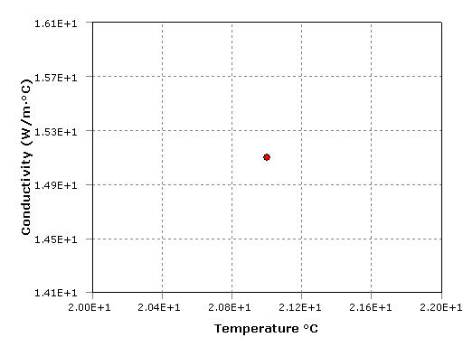
| "Table0001.jpg" | Table A2.1. "Thermal Conductivity vs. Temperature" Thermal Conductivity vs. Temperature |
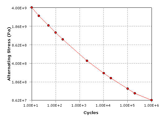
| "Table0002.jpg" | Table A2.2. "Alternating Stress vs. Cycles" Alternating Stress vs. Cycles |
| "Table0003.jpg" | Table A3.1. "Thermal Conductivity vs. Temperature" Thermal Conductivity vs. Temperature |